


automobile rearview mirror shell mould
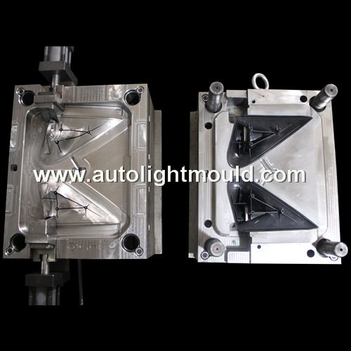
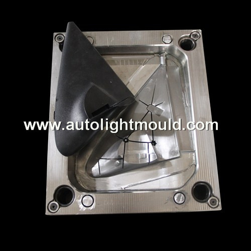
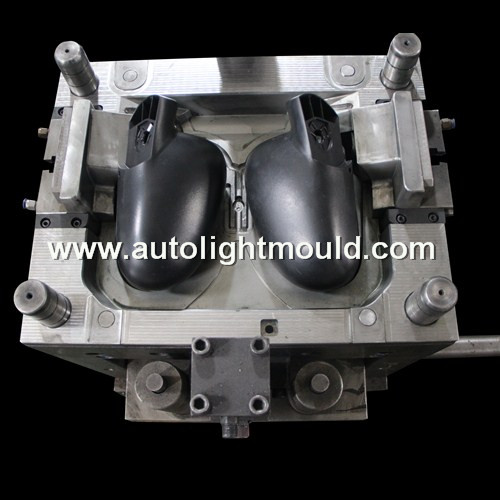
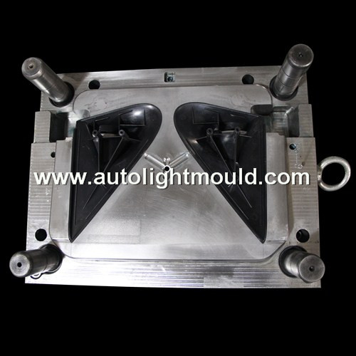
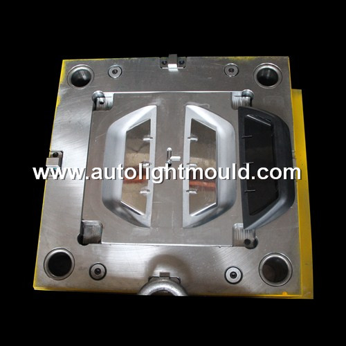
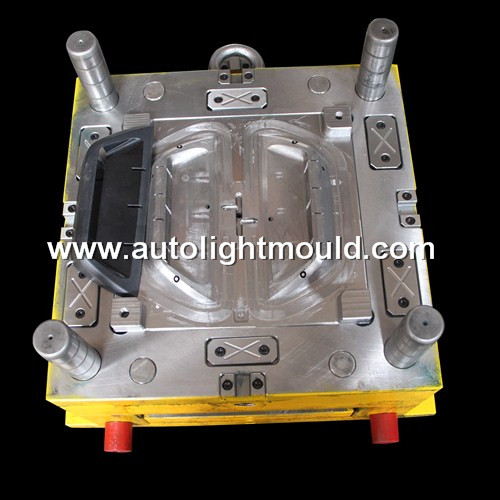
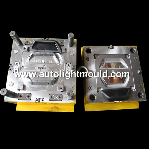
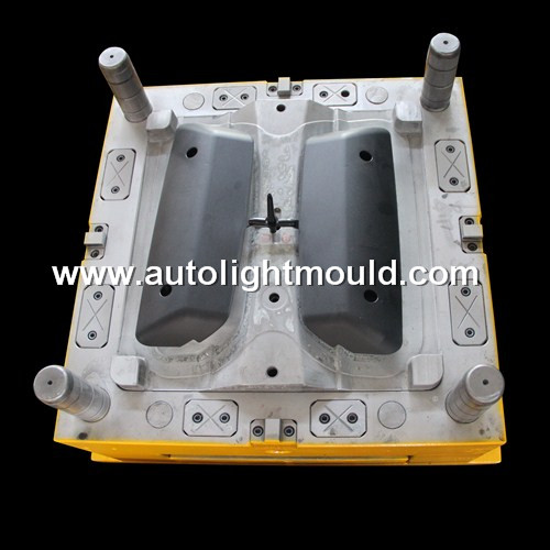
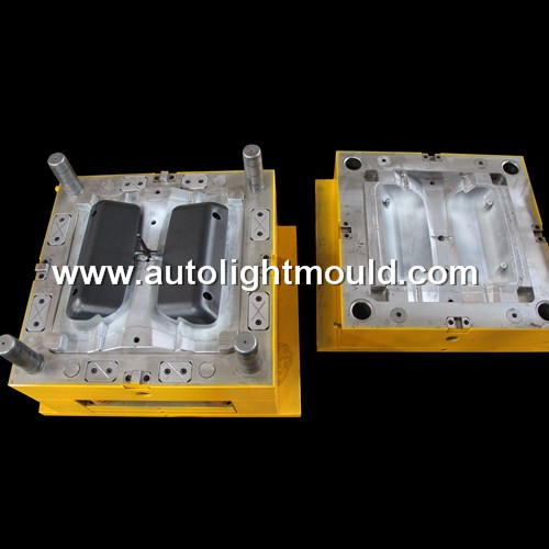
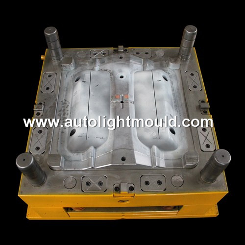
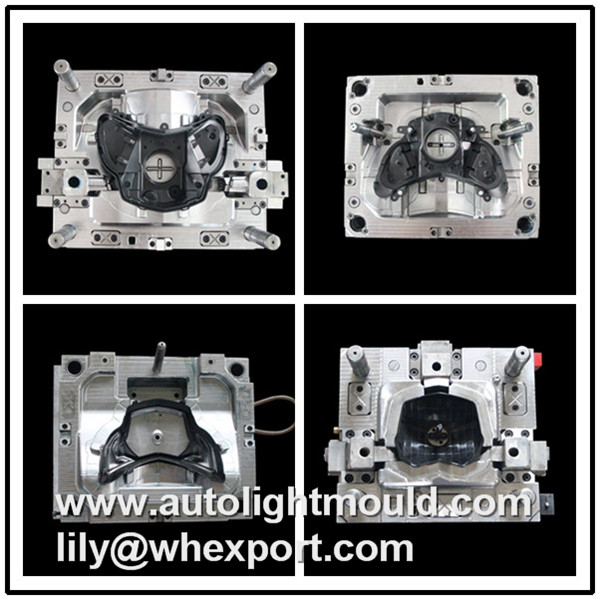
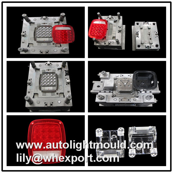
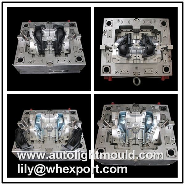
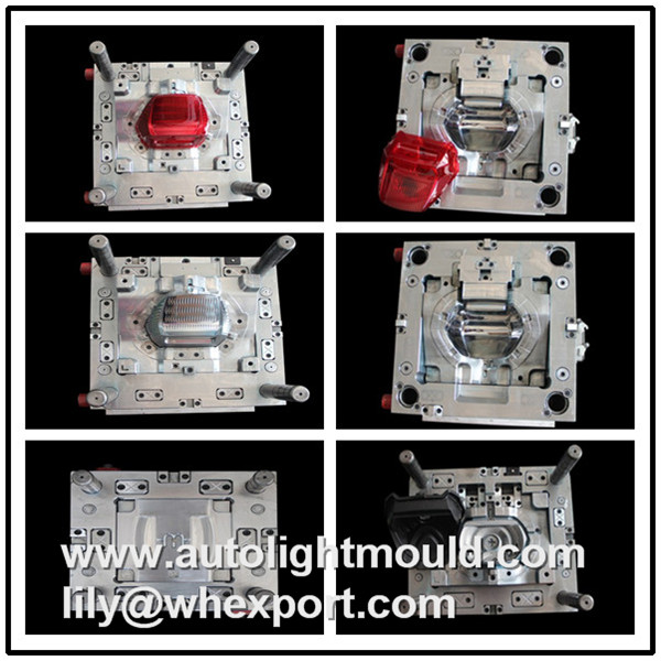
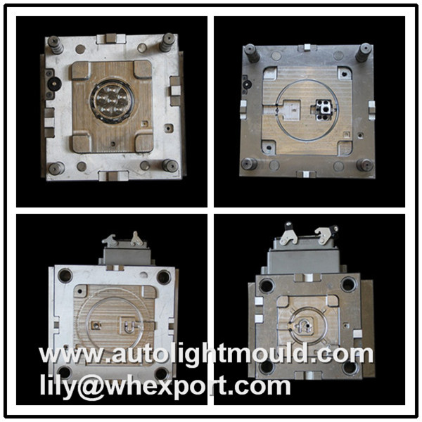
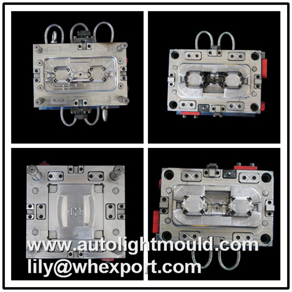
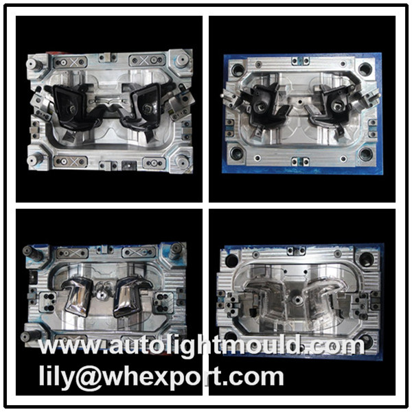
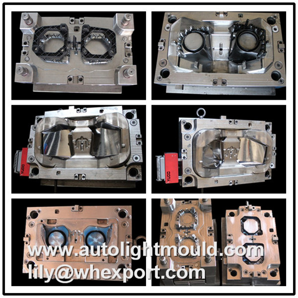
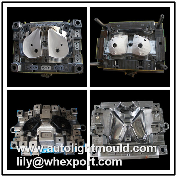
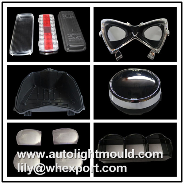
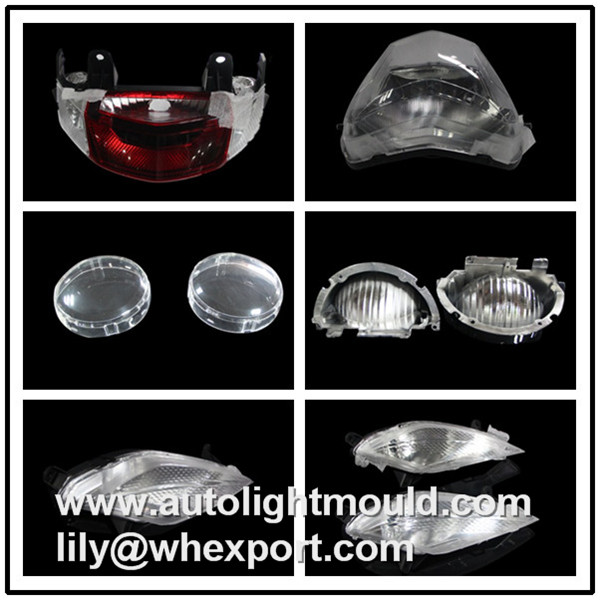
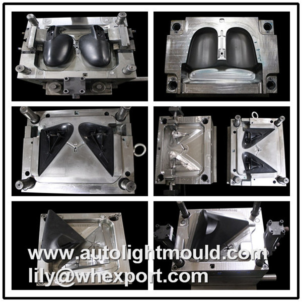
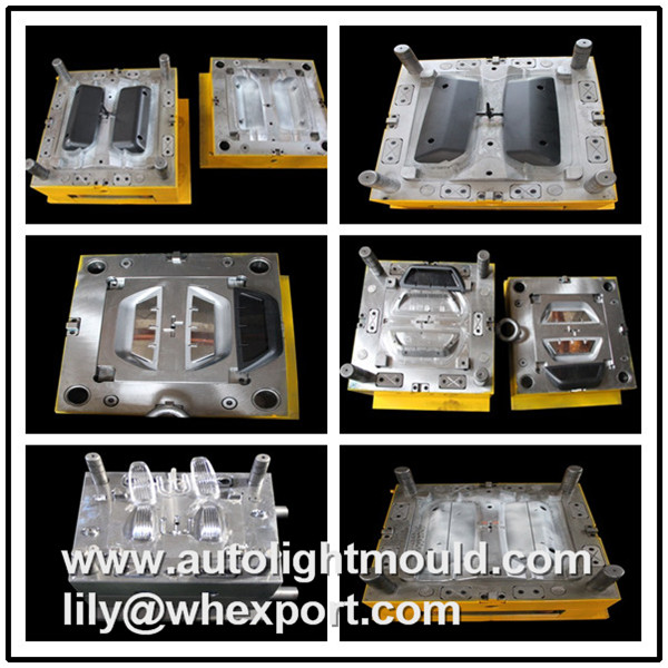
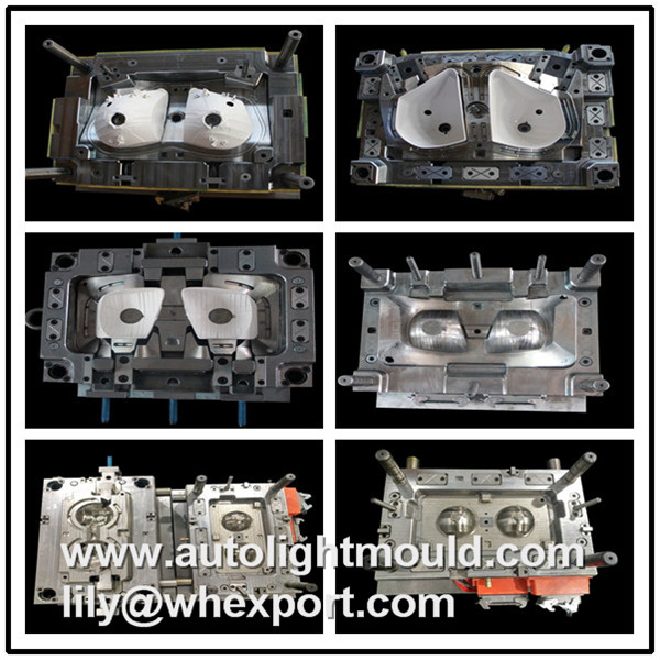
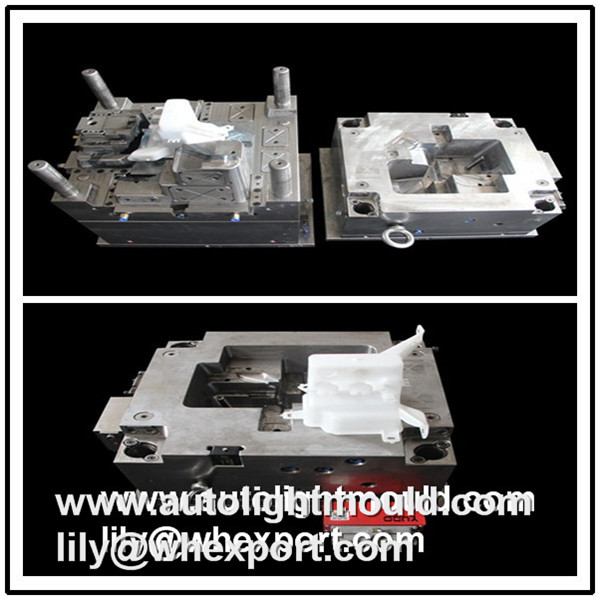
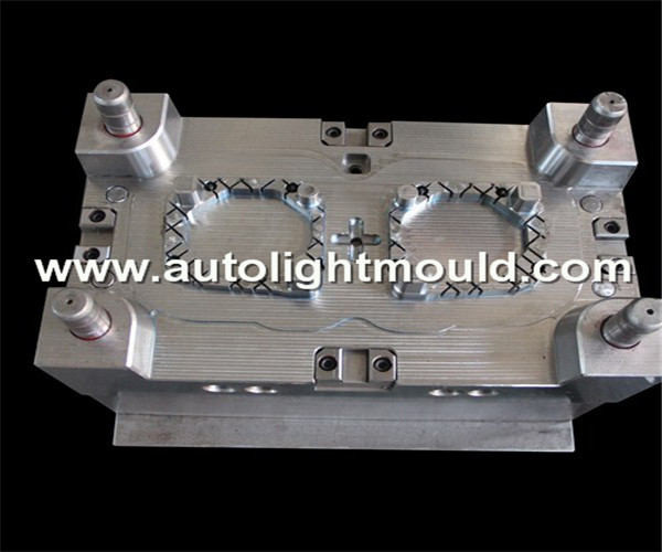
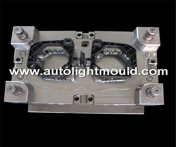
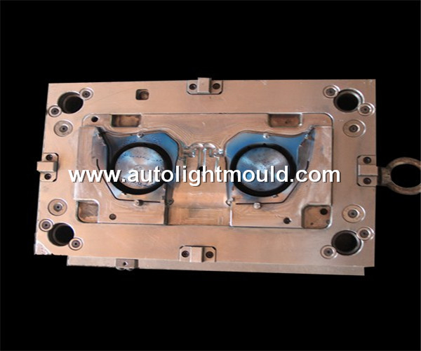
Product design introduction information of automobile rearview mirror mold
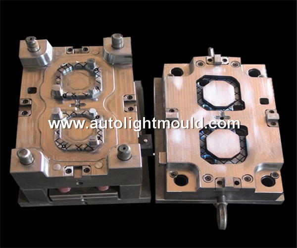
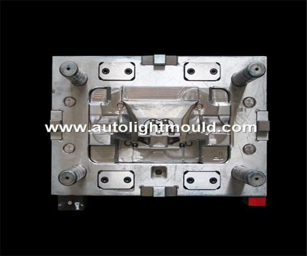
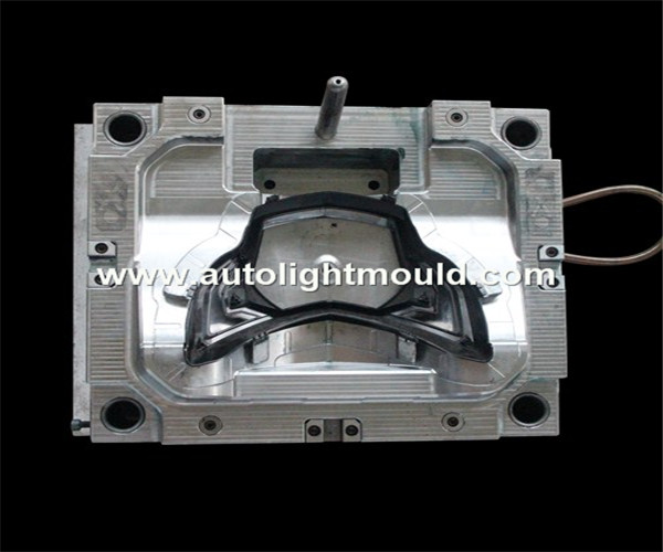
Automobile rear-view mirror mold composition: rear-view mirror frame mold, rear-view mirror base mold, rear-view mirror shell mold, rear-view mirror bracket mold, rear-view mirror rotation axis mold, rear-view mirror mirror base mold, etc. Rear-view mirror products have strict requirements on appearance, high-quality general surface fine line treatment, low-quality general spray paint treatment. According to different models, rearview mirrors are divided into split type and integral type. Mid-to-high-end cars adopt split design, and low-end cars adopt integral design.
Introduction to mold design of automobile rearview mirror
1) Rearview mirror mirror ring mold: product material: ABS
Number of cavities: 1+1, glue feeding method: 2-point hot runner turn to horns to feed glue
2) Rearview mirror base mold, product material: PP+GF45
Number of cavities: 1+1, glue feeding method: glue feeding from the cold runner side or 1 point hot nozzle to the side feeding
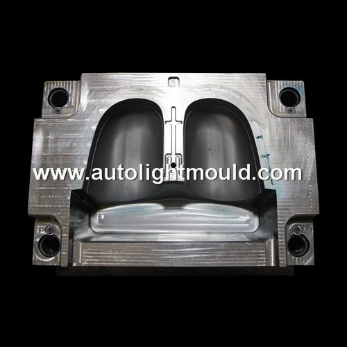
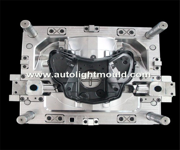
3) Rearview mirror mirror shell mold
Product material: ABS, cavity number: 1+1, glue feeding method: 1 point hot runner to cold runner to horns to feed glue
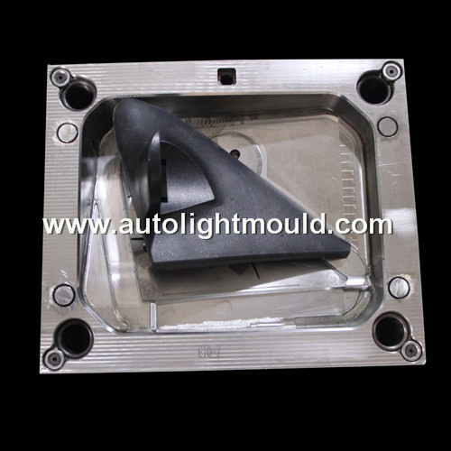
4) Rearview mirror bracket mould
Product material: ABS, cavity number: 1+1, glue feeding method: 1-point open hot runner to cold runner side glue feeding
5) Rearview mirror rotating shaft mould
Product material: ABS, cavity number: 1+1, glue feeding method: 1-point open hot runner to cold runner side glue feeding
6) Rearview mirror mirror base mold
Product material: ABS, cavity number: 1+1, glue feeding method: 1-point open hot runner to cold runner side glue feeding
3. Introduction of rearview mirror mold structure
1) Rearview mirror mirror ring mold
Mould structure: Mirror ring products generally have no structure, but this model has no slanted roof structure.
2) Rearview mirror base mold
Mold structure: rear mold oblique position
3) Rearview mirror mirror shell mold
Mold structure: rear mold oblique row position + rear mold oblique top + oblique top + straight top combined structure
4) Rearview mirror bracket mould
Mold structure: front mold tunnel oblique core pulling + rear mold oblique row position + rear mold straight top
5) Rearview mirror rotating shaft mould
Mold structure: rear mold oblique row position + rear mold oblique top
6) Rearview mirror mirror base mold
Mold structure: front mold tunnel oblique travel position + rear mold oblique travel position + rear mold oblique top
Summary of the mold design of automobile rearview mirror shell
This mold adopts the ejection mechanism of push rod + push block + oblique push block. This is the typical structure of automobile rearview mirror mirror shell mold. When designing this type of mold, attention should be paid to this structure. Manual pickup must be used. When you need to pick up the plastic parts manually, the plastic parts must have space for swinging. This kind of plastic parts that are manually broken out are also used in the design of automobile molds, such as automobile steering columns and throttle covers.
For automobile rearview mirror mirror shell mold, pay attention to:
1. The parting line of the plastic part is on R, and R is on the fixed and movable mold respectively. For this kind of R half-opening or 37-opening mold, in order to invisible the line of appearance during the design, special attention should be paid to make the movable mold core 0.05-0.1mm to avoid segmentation of the plastic part.
2. The fixed and movable die stop, precise positioning must be designed. Avoid dislocation of the fixed and movable mold cores and prevent the plastic parts from segmentation.
3. When the inverted buckle 5 of the mirror housing of this mold is designed as a push block structure, the parts must be manually taken out, and there must be room for swing when taking out the plastic parts.
4. Due to the sharp edges, the edge of the plastic position of the fixed mold of the mirror shell mold must be protected during mold making. It is best to use opaque adhesive paper to protect it to avoid gaps during the transportation process.
5. When designing an oblique slider with a core pulling along the Z axis, it is necessary to pay attention to the slope of the bottom surface of the front end of the oblique slider to be greater than or equal to the angle of the bottom surface of the oblique slider seat to avoid undercutting.
6. The design of the cooling water and spring of the inclined slider must be parallel to the angle of core pulling of the inclined slider to facilitate the processing of the inclined slider. 3. When ordering the oblique slider, it is necessary to order the embryo body along the oblique direction of the oblique slider to facilitate subsequent processing.
7. The bottom of the wear block at the bottom of the inclined slider should be designed to be straight and the wear block should be protruding to avoid interference with the B plate and the stroke stop of the inclined slider when the inclined slider moves backward.
8. Since the oblique slide block must be installed with the fixed mold core to save the jaws, the slider needs to be designed for the mushroom head positioning, and the design of process screws must be paid attention to to facilitate the installation of the fixed mold core and the oblique slide block to save the jaws.
Summary of Die Design of Car Rearview Mirror Bracket
This mold adopts a demolding mechanism of push rod + push block + push block. This is the typical structure of the car rearview mirror bracket mold. When designing this type of mold, attention should be paid to this structure. Manual pickup is required. The plastic parts are manually broken out when the parts are made. For this type of plastic parts, the plastic parts must have room for swing. This kind of plastic parts that are manually broken out are also used in the design of automobile molds, such as automobile steering columns and throttle covers.
For car rearview mirror bracket mould, please pay attention to:
1. The parting line of the plastic part is on R, and R is on the fixed and movable mold respectively. For this kind of R half-opening or 37-opening mold, in order to invisible the line of appearance during the design, special attention should be paid to make the movable mold core 0.05-0.1mm to avoid segmentation of the plastic part.
2. The fixed and movable die stop, precise positioning must be designed. Avoid dislocation of the fixed and movable mold cores and prevent the plastic parts from segmentation.
3. When the mold undercuts 3 and 4 are designed as a push block structure, the parts must be taken manually, and there must be room for swinging when taking out the plastic parts.
4. Because of the sharp edges, the edge of the bracket mold fixed core glue position must be protected during mold making. It is best to protect it with opaque adhesive paper to avoid the gap in the handling process.
5. Since the oblique slider must be installed with the fixed mold core to save the jaws, the slider needs to be designed for the mushroom head positioning. Also pay attention to the design of the process screws to facilitate the installation of the fixed mold core and the oblique slider to save the jaws.
Summary of mold design for automobile rearview mirror base
This mold adopts the demolding system of push rod + push tube + mechanical push, and the temperature control system of"straight-through water pipe + inclined water pipe + water well"and the inclined slider core-pulling system.
In the design of automotive mold temperature control system, there are mainly the following two combinations:
(1) The first combination form: straight-through water pipe + inclined water pipe + water well;
(2) The second combination form: straight-through water pipe + well + inclined water pipe.
The difference between the two forms is that between the inclined water pipe and the water well, the former is the preferred use of the inclined water pipe, while the latter is the preferred use of the water well. The focus of these two combinations is different, so the effect is also different.
The advantages of the first form are uniform cooling everywhere in the cavity, short forming cycle, high quality plastic parts, suitable for molds with high requirements and high appearance performance requirements, such as automobile front and rear bumpers, and automobile upper and lower instrument panel bodies And automobile left and right door panels and other interior and exterior injection molds. The disadvantage is that the processing cost is high, and it is mainly suitable for molds of European and American customers.
The advantage of the second form is that the processing cost is lower and the processing is convenient and quick. The disadvantage is that too many design wells on the mold have a certain impact on the strength of the mold. The cavity cooling effect is worse than that of the first type. It is more used in Japanese and Chinese domestic automobile molds.
The fixed and movable molds of this mold are slammed through, and the inserting position is used for insert processing in order to avoid damage during production. In order to avoid difficulty in venting and filling the bone position with a depth of more than 10mm in the movable mold, inserts are also used. Due to the special shape of this plastic part, in order to avoid the plastic part from sticking to the fixed mold, the fixed mold elastic block mechanism is designed in the fixed mold to assist the ejection of the plastic part and keep the plastic part in the movable mold, thus avoiding the plastic part sticking. The phenomenon of fixed mold occurs.
Summary of mold design for automobile rearview mirror mirror seat
The mold adopts the demolding mechanism of"push rod + inclined top + spring + injection molding machine pull-back", adopts the side core pulling structure of fixed mold tunnel inclined slider and"inclined guide post + slider". There are many sliders and a large core-pulling area. The rubber surface of the slider needs to be treated with skin texture, and the appearance requirements are high. For this mold, the pre-deformation treatment of plastic parts is very important. To solve the warpage deformation of the plastic parts after molding, pre-deformation is a priority plastic part processing technology. The appearance of this mold requires high clamping lines. The slide block and the fixed mold are clamped together to save mold, and the positioning of the slide block must be stable and reliable. According to experience, automobile plastic parts are easy to be scratched after the skin texture, so it is necessary to ensure that the stripping angle of the skin texture is above 5 degrees.
This mold has many sliders and two fixed mold tunnel inclined sliders, as well as many sliders and fixed mold inserts. Therefore, the mold process is more complicated. In addition to ordinary machine tool processing, CNC, deep hole drilling, and five Axis CNC, spark machine, wire cutting and other high-precision machine tools are used for processing. The production process is complicated and the production is difficult.
According to the structural characteristics, material characteristics, surface quality of plastic parts and batch requirements of automobile rearview mirror mirror holders, a cold runner injection method is designed to improve the fluidity of molten plastic during injection molding and improve plastic parts The filling effect saves the condensate of the runner system after molding, improves the molding cycle of the plastic part, and improves the production efficiency of the plastic part. Since the mass production of this mold, the core pulling is stable and reliable due to the reasonable design of each mechanism. This mold has successfully used pre-deformation processing technology and mold flow analysis technology to solve the problem of plastic part warpage and deformation, and has obtained customer satisfaction. It is a successful example in recent production and can be called the mold structure of automobile rearview mirror. Classic Case. .
Otomobil dikiz aynası kalıbının ürün tasarımı tanıtım bilgisi
Otomobil dikiz aynası kalıbı bileşimi: dikiz aynası çerçeve kalıbı, dikiz aynası taban kalıbı, dikiz aynası kabuk kalıbı, dikiz aynası braketi kalıbı, dikiz aynası dönme eksen kalıbı, dikiz aynası ayna tabanı kalıbı, vb. Dikiz aynası ürünleri, görünüm, yüksek kaliteli genel yüzey ince çizgi işlemi, düşük kaliteli genel sprey boya işlemi konusunda katı gerekliliklere sahiptir. Farklı modellere göre, dikiz aynaları bölünmüş tip ve entegre tip olarak ikiye ayrılır Orta-üst-uç arabalar bölünmüş tasarımı benimser ve düşük-uç arabalar bütünsel tasarımı benimser.
Otomobil dikiz aynasının kalıp tasarımına giriş
1) Dikiz aynası ayna halkası kalıbı: ürün malzemesi: ABS
Boşluk sayısı: 1 + 1, tutkal besleme yöntemi: 2 noktalı sıcak yolluk, tutkal beslemek için boynuzlara döner
2) Dikiz aynası taban kalıbı, ürün malzemesi: PP + GF45
Boşluk sayısı: 1 + 1, tutkal besleme yöntemi: soğuk yolluk tarafından tutkal beslemesi veya yan beslemeye 1 nokta sıcak nozul
3) Dikiz aynası kabuk kalıbı
Ürün malzemesi: ABS, boşluk numarası: 1 + 1, tutkal besleme yöntemi: 1 nokta sıcak yolluktan soğuk yolluktan boynuzlara tutkal beslemek için
4) Dikiz aynası braket kalıbı
Ürün malzemesi: ABS, boşluk numarası: 1 + 1, tutkal besleme yöntemi: 1 noktalı açık sıcak yolluktan soğuk yolluk yan tutkal beslemesine
5) Dikiz aynası döner şaft kalıbı
Ürün malzemesi: ABS, boşluk numarası: 1 + 1, tutkal besleme yöntemi: 1 noktalı açık sıcak yolluktan soğuk yolluk yan tutkal beslemesine
6) Dikiz aynası taban kalıbı
Ürün malzemesi: ABS, boşluk numarası: 1 + 1, tutkal besleme yöntemi: 1 noktalı açık sıcak yolluktan soğuk yolluk yan tutkal beslemesine
3. Dikiz aynası kalıp yapısının tanıtımı
1) Dikiz aynası ayna halkası kalıbı
Kalıp yapısı: Ayna halkalı ürünler genellikle yapıya sahip değildir ancak bu modelin eğimli çatı yapısı yoktur.
2) Dikiz aynası taban kalıbı
Kalıp yapısı: arka kalıp eğik pozisyonu
3) Dikiz aynası kabuk kalıbı
Kalıp yapısı: arka kalıp eğik pozisyon + arka kalıp eğik üst + eğik üst + düz üst kombine yapı
4) Dikiz aynası braket kalıbı
Kalıp yapısı: ön kalıp tüneli eğik çekirdek çekme + arka kalıp eğik sıra konumu + arka kalıp düz üst
5) Dikiz aynası döner şaft kalıbı
Kalıp yapısı: arka kalıp eğik sıra konumu + arka kalıp eğik üst
6) Dikiz aynası taban kalıbı
Kalıp yapısı: ön kalıp tüneli eğik hareket konumu + arka kalıp eğik hareket konumu + arka kalıp eğik üst
Otomobil dikiz aynası kabuğunun kalıp tasarımının özeti
Bu kalıp, itme çubuğu + itme bloğu + eğik itme bloğunun çıkarma mekanizmasını benimser.Bu, otomobil dikiz aynası kabuk kalıbının tipik yapısıdır.Bu tür bir kalıp tasarlarken, bu yapıya dikkat edilmelidir.Manuel toplama kullanılmalıdır. Plastik parçaları elle kaldırmanız gerektiğinde, plastik parçalarda sallanma alanı olmalıdır. Manuel olarak parçalanan bu tür plastik parçalar, otomobil direksiyon kolonları ve gaz kelebeği kapakları gibi otomobil kalıplarının tasarımında da kullanılır.
Otomobil dikiz aynası aynası kabuk kalıbı için şunlara dikkat edin:
1. Plastik parçanın ayırma çizgisi R üzerindedir ve R sırasıyla sabit ve hareketli kalıp üzerindedir. Bu tür bir R yarı açılır veya 37 açılır kalıp için, tasarım sırasında görünüm çizgisini görünmez hale getirmek için, plastik parçanın bölünmesini önlemek için hareketli kalıp göbeğinin 0,05-0,1 mm olmasına özel dikkat gösterilmelidir.
2. Sabit ve hareketli kalıp durdurucu, hassas konumlandırma tasarlanmalıdır. Sabit ve hareketli kalıp maçalarının yerinden çıkmasını önleyin ve plastik parçaların bölünmesini önleyin.
3. Bu kalıbın ayna yuvasının ters çevrilmiş tokası 5 bir itme blok yapısı olarak tasarlandığında, parçalar manuel olarak çıkarılmalı ve plastik parçalar çıkarılırken salınım için yer olmalıdır.
4. Keskin kenarlar nedeniyle, ayna kabuk kalıbının sabit kalıbının plastik pozisyonunun kenarı kalıp yapımı sırasında korunmalıdır. Nakliye işlemi sırasında boşlukları önlemek için en iyisi opak yapışkan kağıt kullanmaktır.
5. Z ekseni boyunca çeken bir göbeğe sahip eğik bir araba tasarlarken, alttan kesilmeyi önlemek için eğik sürgü koltuğunun alt yüzeyinin açısına eşit veya bu eğik sürgülü arabanın ön ucunun alt yüzeyinin eğiminin daha büyük olmasına dikkat etmek gerekir.
6. Eğimli sürgünün soğutma suyu ve yayının tasarımı, eğimli sürgünün işlenmesini kolaylaştırmak için eğimli sürgünün çekirdek çekme açısına paralel olmalıdır. 3. Eğik kaydırıcıyı sipariş ederken, sonraki işlemeyi kolaylaştırmak için embriyo gövdesini eğik kaydırıcının eğik yönü boyunca sıralamak gerekir.
7. Eğimli sürgünün altındaki aşınma bloğunun tabanı düz olacak şekilde tasarlanmalı ve eğimli sürgü geriye doğru hareket ettiğinde eğimli sürgünün durma noktası ve B plakası ile etkileşimi önlemek için aşınma bloğu çıkıntılı olmalıdır.
8. Eğik kayar bloğun çeneleri kurtarmak için sabit kalıp göbeği ile birlikte takılması gerektiğinden, sürgü mantar kafa konumlandırması için tasarlanmalıdır ve çeneleri kurtarmak için sabit kalıp göbeğinin ve eğik kayma bloğunun kurulumunu kolaylaştırmak için işlem vidalarının tasarımına dikkat edilmelidir.
Araç Dikiz Aynası Braketinin Kalıp Tasarımının Özeti
Bu kalıp, itme çubuğu + itme bloğu + itme bloğunun bir kalıptan çıkarma mekanizmasını kullanır.Bu, araba dikiz aynası braket kalıbının tipik yapısıdır.Bu tür bir kalıp tasarlanırken, bu yapıya dikkat edilmelidir.Manuel toplama gereklidir. Plastik parçalar, parçalar yapılırken manuel olarak kırılır.Bu tip plastik parçalar için, plastik parçalarda salınım yeri olmalıdır. Manuel olarak parçalanan bu tür plastik parçalar, otomobil direksiyon kolonları ve gaz kelebeği kapakları gibi otomobil kalıplarının tasarımında da kullanılır.
Araba dikiz aynası braket kalıbı için lütfen şunlara dikkat edin:
1. Plastik parçanın ayırma çizgisi R üzerindedir ve R sırasıyla sabit ve hareketli kalıp üzerindedir. Bu tür bir R yarı açılır veya 37 açılır kalıp için, tasarım sırasında görünüm çizgisini görünmez hale getirmek için, plastik parçanın bölünmesini önlemek için hareketli kalıp göbeğinin 0,05-0,1 mm olmasına özel dikkat gösterilmelidir.
2. Sabit ve hareketli kalıp durdurucu, hassas konumlandırma tasarlanmalıdır. Sabit ve hareketli kalıp maçalarının yerinden çıkmasını önleyin ve plastik parçaların bölünmesini önleyin.
3. Kalıp alt oyukları 3 ve 4 itme bloğu yapısı olarak tasarlandığında, parçalar elle alınmalı ve plastik parçalar çıkarılırken sallanma yeri olmalıdır.
4. Keskin kenarlar nedeniyle, braket kalıbının kenarı sabit maça tutkal pozisyonu kalıp yapımı sırasında korunmalıdır.İşlem sürecinde boşluğu önlemek için opak yapışkan kağıtla korumak en iyisidir.
5. Eğik sürgü, çeneleri kurtarmak için sabit kalıp göbeği ile birlikte takılması gerektiğinden, sürgü mantar kafa konumlandırması için tasarlanmalıdır.Ayrıca, sabit kalıp çekirdeğinin ve çeneleri kurtarmak için eğik sürgünün kurulumunu kolaylaştırmak için işlem vidalarının tasarımına da dikkat edin.
Otomobil dikiz aynası tabanı için kalıp tasarımının özeti
Bu kalıp, itme çubuğu + itme borusu + mekanik itmenin sökme sistemini ve"düz su borusu + eğimli su borusu + su kuyusu"sıcaklık kontrol sistemini ve eğimli kaydırıcı çekirdek çekme sistemini benimser.
Otomotiv kalıp sıcaklık kontrol sistemi tasarımında, esas olarak aşağıdaki iki kombinasyon vardır:
(1) İlk kombinasyon şekli: düz su borusu + eğimli su borusu + su kuyusu;
(2) İkinci kombinasyon şekli: düz su borusu + kuyu + eğimli su borusu.
İki form arasındaki fark, eğimli su borusu ile su kuyusu arasında, birincisi eğimli su borusunun tercih edilen kullanımı, ikincisi ise su kuyusunun tercih edilen kullanımıdır. Bu iki kombinasyonun odak noktası farklıdır, bu nedenle etki de farklıdır.
İlk formun avantajları, boşlukta her yerde tek tip soğutma, kısa şekillendirme döngüsü, yüksek kaliteli plastik parçalardır, yüksek gereksinimleri olan kalıplar için uygun ve otomobil ön ve arka tamponları gibi yüksek görünüm performansı gereksinimleri ve otomobil üst ve alt gösterge paneli gövdeleri Ve otomobil sol ve sağ kapı panelleri ve diğer iç ve dış enjeksiyon kalıpları. Dezavantajı ise işleme maliyetinin yüksek olması ve esas olarak Avrupalı ve Amerikalı müşterilerin kalıpları için uygun olmasıdır.
İkinci formun avantajı, işlem maliyetinin daha düşük olması ve işlemenin rahat ve hızlı olmasıdır. Dezavantajı, kalıp üzerindeki çok fazla tasarım kuyusunun kalıbın mukavemeti üzerinde belirli bir etkiye sahip olmasıdır.Kavite soğutma etkisi birinci tipe göre daha kötüdür.Japon ve Çin yerli otomobil kalıplarında daha çok kullanılmaktadır.
Bu kalıbın sabit ve hareketli kalıpları ezilir ve üretim sırasında hasar görmemesi için geçme pozisyonu uç işlemede kullanılır. Hareketli kalıpta derinliği 10 mm'den fazla olan kemik pozisyonunun havalandırılması ve doldurulmasında zorluk yaşanmaması için insertler de kullanılmaktadır. Bu plastik parçanın özel şekli sayesinde, plastik parçanın sabit kalıba yapışmasını önlemek için sabit kalıpta elastik blok mekanizması, plastik parçanın dışarı çıkmasına yardımcı olmak ve plastik parçayı hareketli kalıp içinde tutmak, böylece plastik parçanın yapışmasını önlemek için sabit kalıp içerisinde tasarlanmıştır. Sabit küf olgusu ortaya çıkar.
Otomobil dikiz aynası aynası koltuğu için kalıp tasarımının özeti
Kalıp,"itme çubuğu + eğimli üst + yay + enjeksiyon kalıplama makinesi geri çekme"nin kalıptan çıkarma mekanizmasını benimser, sabit kalıp tüneli eğimli sürgüsünün ve"eğimli kılavuz direği + sürgüsünün"yan çekirdek çekme yapısını benimser. Çok sayıda kaydırıcı ve geniş bir çekirdek çekme alanı vardır Kaydırıcının kauçuk yüzeyinin cilt dokusu ile işlenmesi gerekir ve görünüm gereksinimleri yüksektir. Bu kalıp için plastik parçaların ön deformasyon işlemi çok önemlidir.Plastik parçaların kalıplamadan sonra çarpık deformasyonunu çözmek için ön deformasyon öncelikli bir plastik parça işleme teknolojisidir. Bu kalıbın görünümü yüksek sıkıştırma hatları gerektirir Kayar blok ve sabit kalıp kalıptan tasarruf etmek için birbirine kenetlenir ve kayar bloğun konumlandırması sabit ve güvenilir olmalıdır. Tecrübelere göre otomobil plastik kısımlarının cilt dokusundan sonra kolayca çizilmesi kolay olduğundan cilt dokusunun sıyrılma açısının 5 derecenin üzerinde olmasını sağlamak gerekir.
Bu kalıbın birçok sürgüsü ve iki sabit kalıp tünel eğimli sürgüsü ile birlikte birçok sürgü ve sabit kalıp eki vardır.Bu nedenle, kalıp işlemi daha karmaşıktır.Sıradan takım tezgahı işleme, CNC, derin delik delme ve beş Eksen CNC, kıvılcım makinesi, tel kesme ve diğer yüksek hassasiyetli takım tezgahları işleme için kullanılır. Üretim süreci karmaşıktır ve üretim zordur.
Otomobil dikiz aynası koltuğunun yapısal özelliklerine, malzeme özelliklerine, plastik parçaların yüzey kalitesine ve parti gereksinimlerine göre, enjeksiyon kalıplama işlemi sırasında erimiş plastiğin akışkanlığını artırmak ve plastik parçaları iyileştirmek için bir soğuk yolluk enjeksiyon yöntemi tasarlanmıştır. Doldurma etkisi, kalıplamadan sonra kızak sisteminin yoğuşmasını korur, plastik parçanın kalıplama döngüsünü iyileştirir ve plastik parçanın üretim verimliliğini artırır. Bu kalıbın seri üretiminden bu yana, her mekanizmanın makul tasarımı nedeniyle maça çekme kararlı ve güvenilirdir. Bu kalıp ön deformasyon işleme teknolojisini ve kalıp akış analizi teknolojisini başarıyla kullanarak plastik parça eğrilmesi ve deformasyon problemini çözerek müşteri memnuniyetini sağlamıştır.Son üretimde başarılı bir örnek olup otomobil dikiz aynasının kalıp yapısı olarak adlandırılabilir. Klasik Kılıf. .


+86 15267697871

younger8@autolightmould.com
